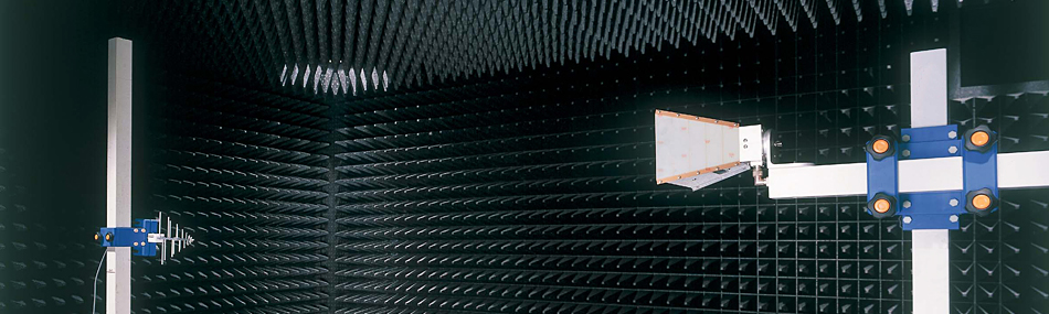
Anechoic Chamber for Antenna Evaluation
- Can be used for very wide band of frequency from FM waves to millimeter waves
- Quiet zone characteristics offered based on indigenous simulation
- PFP series of electromagnetic wave absorbers are used. Absorption of moisture allows us to offer highly durable electromagnetic anechoic chambers that do not deteriorate
| Free space standing wave method | |
| 10GHz | |
| 3.0m | |
| Horizontal polarized wave / Perpendicular polarized wave | |
| 1.929m from transmission/reception shielded surface (center height of electromagnetic wave dark box) | |
| W2.0 × H2.0 m | |
| Inside 1.5m diameter sphere at the central height of 1.929m (center of electromagnetic wave dark box) from the metal floor at a distance of 3m from quiet zone (QZ) transmission antenna |
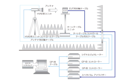
- System configuration, but it can be used for evaluation of various antennas
- Accurate and prompt measurement with GP-IB control
- Software can be customized as per the devices available
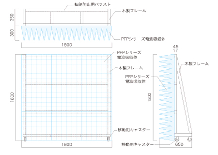
- Portable screen made of PFP electromagnetic wave absorber
- Can be used for various antenna experiments
- Available in three sizes of W600mm W1200mm W1800mm
 |
 |